Lund, Sweden, October 2010
This web page is written to help you understand how the digital and analog audio processing was implemented in the Commodore 64 demo "Cubase64" written by Pex 'Mahoney' Tufvesson in October 2010. The pdf version of this text can be found here: Cubase64_White_Paper_by_Pex_Mahoney_Tufvesson.pdf. The complete source code and binaries are here: Cubase64_by_Pex_Mahoney_Tufvesson.zip
To fully enjoy this text, some knowledge about digital audio and computer programming is required. You do not really need knowledge of 6502 assembly programming or Commodore 64 hardware programming.
Keywords: 8-bit Digital Audio Processing, Commodore 64, 6502 CPU, extreme optimizations
|
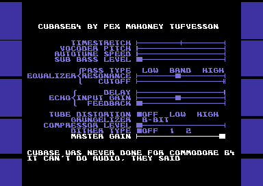
Figure 1. Screen Shot
This white paper will describe how to manage to do 11 audio effects, in real time, simultaneously, with a home computer from 1982.
These are a couple of versions of it: Cubase64 - Live at the release party. Cubase 64 - on an emulator. Cubase64 - on Commodore 64. You'll have to live with the advertisements, since the video is detected as containing copyrighted audio. ;)
If you're not happy with a video version of it, go and grab an emulator of the Commodore 64. There are many, but I'd recommend the vice emulator at http://www.viceteam.org
With any modern computer and operating system, the Commodore 64 can be almost flawlessly emulated. You'll have cope with the monitor refresh being out of sync with the PAL TV's 50Hz video, though.
And, please make sure that your emulator is using the resid-fp sound emulation algorithm, for the 6581 version of the SID sound chip. The 8580 SID chip works too, but has less interesting filters.
Or, if you're the happy owner of the real deal, please run Cubase64 on your Commodore 64. If you don't own a Commodore 64, it's a flea-market bargain at an approximate price of 50 SEK, €5, $5 or something similar. Oh! The joys of cheap retro computing!
This is a list of all the requirements for Cubase64:
Use a Commodore 64 home computer with a CPU constructed back in 1975, more than 35 years ago. The 6502 CPU used about 4000 transistors, compared to a recent 2010 Intel CPU with 1.17 billion transistors. The SID sound chip was designed in 1981, and is described in the U.S. Patent 4,677,890, which was filed on February 27, 1983, and issued on July 7, 1987. The patent expired on July 7, 2004.
Since the Commodore 64 don't have an accessible audio-in port, it plays the complete song "Tom's Diner" by Suzanne Vega. More than 2 minutes of audio. Frequency range 20-16000Hz. Mono.
Time stretch. Will play the song with 0-200% speed without changing the pitch. This algorithm uses the Fast Fourier Transform to capture the frequency spectrum of the audio, and then uses the Inverse Fourier Transform with altered phase information for reconstructing the original audio with a new time scale.
Vocoder. For getting a robotic alien-pitched sound. Also an algorithm based on the Fast Fourier Transform.
Auto-Tune. Will make the singing get closer to "perfect pitch". Works by analyzing the pitch, correcting it and then recalculating the audio using a pitch vocoder to compensate for the incorrect singing.
Sub bass synthesizer. Will find the base frequency of the input signal and synthesize frequencies two octaves below the fundamental frequency.
Equalizer. Will filter frequencies. Three different filter types can be combined: Low pass filter - will remove mid and high frequencies, Band pass filter - will remove low and high frequencies and High pass filter - will remove mid and low frequencies. This equalizer also comes with a resonance setting, which will make a distinct peak in the frequency spectrum around the cutoff frequency.
Echo. Will feedback a certain amount of the sound, just as if standing in a small bathroom or a by a huge stone wall. The echo delay is selectable from 0.0 millisecond to 32 milliseconds. The input gain will prevent distortion in the audio computation. The feedback gain will set how much of the delayed sound that will remain.
Tube distortion. Analogue electronics have a non-linear frequency response that the human ears easily detects. Some people love it, some don't. This digital simulation of analogue behavior will mimic the behavior of a non-linear amplification stage.
Grungelizer. This effect will limit the number of quantization values that the audio will use. With CD-quality audio, there's 65536 levels to choose from. This grungelizer will give your the option to use 256, 128, 64, 32, 16, 8, 4 or 2 levels. This roughly translates to "the number of different places" your loudspeaker membrane will travel to.
Compressor. This audio effect will analyze the volume level of the audio, and raise the volume for silent passages. When applied to a human voice, the sound will appear to be closer to you.
Dithering. This audio effect will add a small amount of noise to the output signal, in order to mask the quantization noise introduced when changing the volume or accuracy in the digital domain. Type 1 dithering is continuous, while Type 2 dithering is program dependent and hence is silent when the incoming audio is silent.
Master Gain. This audio effect will change the output volume for the audio.
All of these effect can be turned on simultaneously.
The 6502 central processing unit (CPU) in the Commodore 64 computer is run at almost 1MHz. This means that there's a clock ticking 985.248 times per second. I have chosen a sample playback rate of 7812.5 Hz, which means that we roughly have 126 clock cycles available to calculate and play a new sample:
Available clock cycles per sample=985248 / 7812.5 = 126
However, the CPU is stalled sometimes, since there are "more important" chips that need to use the CPU's memory. The video chip, called VIC-II, will steal the memory bus whenever it needs to fetch new data for displaying on your TV set. This happens on every row, and there's 25 rows on the display, and it needs to fetch 40 characters to display, and it does this 50 times per second.
Stolen clock cycles per second = 25 * 40 * 50 = 50000
Divide this by the playback rate (7812.5 Hz), and we get
Available clock cycles per sample with graphics = (985248 - 25 * 40 * 50) / 7812.5 = 119.5
This is an average value, since we sometimes have 126 clock cycles available, and sometimes just 126-40 = 86 clock cycles available.
Now, if only this was the complete picture. It isn't. The Commodore 64 has a sound chip that wasn't designed for playing samples. Since there's not much available memory, they did not intend the SID chip to play samples - 64kB with 8kHz sample rate will give you a some 8 seconds of sound to play. There was no need for sample playback.
So, we have to fool the SID chip to play samples, even though it only has the means of playing either a continuous triangle waveform, sawtooth waveform, pulse-width waveform or noise waveform. This is done by using the triangle waveform, resetting the oscillator with an undocumented test-bit originally implemented for factory testing, setting the accumulator frequency to change the increment speed of the accumulator, and then after an exact number of clock cycles enable the triangle waveform output just briefly, practically emulating a sample-and-hold filter that will keep the analog output fixed at a certain voltage. This requires 4 SID register writes, which will use
4 writes * (Clocks per LDA instruction + Clock per STA instruction) = 4 * (2 + 4) = 24 clock cycles.
We now have between (126-24=102) to (86-24=62) clock cycles available per sample. Sounds complicated? Yes it is. To make matters worse, the 6502 CPU that will have to trigger all these registers in the SID chip will need to be completely synchronized for _every_ sample that is output. Else, the accumulator will not output a steady amplitude for a given desired output value.
Thankfully, there are support chips in the Commodore 64 that will help us. But just a little. The 6526 CIA peripheral chip is used to interrupt the 6502 CPU every 126th clock cycle.
So far, so good. But, this interrupt is not stable. The 6502 CPU was executing something when the 6526 CIA chip said "please stop what you're doing and come with me". The 6502 response is "yes, I will come, but please let me finish this first". Which means that the 6502 CPU will execute the first NMI assembly instructions something between 8 and 14 clock cycles later. But we need to know exactly how many cycles off we are.
This can be handled. The 6526 CIA has a byte register that will hold the current value of the timer, which is incremented by 1 every clock cycle. We will have to read this value, and compensate for the clock cycles "lost" during the interrupt phase.
But, all of this will require a number of clock cycles to be "wasted". A rough calculation is that the interrupt will take between 20-30 clock cycles with all of these features enabled.
Which means that we have between (102-30=72) and (62-30=32) clock cycles available for calculating a sample.
32 clock cycles for a sample is not much. You need to keep in mind that a simple operation like multiplying two 8-bit numbers takes between 150 and 400 clock cycles with a 6502 CPU, since it has no hardware support for multiplication. An 8-bit addition, however, will take 2 clock cycles, which is the fastest instruction the 6502 can do.
So, we need to be able to utilize "the average number" of available clock cycles for calculations, since on-the-fly calculations of samples won't be be possible when the worst-case occurs. We will have to use a sound buffer.
This sound buffer will be a FIFO, First-In-First-Out structure. The 6502 CPU already has a hardware stack that could help us. But, the 6502 stack is a "Last-In-First-Out" structure. And, it is already in use by the 6502 interrupt handler and subroutine return addresses. Normally, when the 6502 wants to put a value at the stack, it uses a "PHA" instruction, which will write the value to memory, and decrease the stack pointer. When it wants to get the value back, it uses a "PLA" instruction, which grabs the value, and increases the stack pointer. For writing sound to the sound buffer in the stack, we can only use the PHA instruction. The PLA instruction cannot be used for reading, since the hardware implementation on PLA in the 6502 CPU only supports reading the last value written on the stack.
We will have to read the sound buffer with an LDA-instruction, and decrement our sound buffer pointer manually. Thus, the 6502 stack will wrap, overwriting old values with new ones, and any occurring interrupt will overwrite audio data as well. But, as long as the "render thread" and "playback thread" stay synchronized, we're good.
So far, we have two threads which needs to run: the audio rendering thread, and the audio playback thread. To make smooth updates to the TV screen, we also need a third thread, the video update thread. This is also an interrupt, but it occurs twice every frame (100Hz). It takes care of joystick handling, changes on screen and changes to audio parameters. It also does the neat trick of disabling the upper and lower border on the Commodore 64 video chip, to make the visuals nicer.
So, the priority of the threads are:
1. The audio playback thread (which uses a NMI interrupt)
2. The video update/audio parameter thread (which uses the IRQ synced to the TV)
3. The audio render thread
This means that the audio rendering will get "the rest of the available clock cycles" when the playback and the video update has taken what they need. Without the video update thread, we did have between 32-72 clock cycles available per sample. With the video update thread, we have in average 40 clock cycles per sample. We did not gain much clock cycles by introducing the sound buffer, but we did get the possibility of changing the graphics presented on the TV.
An assembly instruction on the 6502 CPU takes between 2 and 8 clock cycles to run. 40 clock cycles will approximately be 40/3 = 13 assembly instructions.
So, the answer to the question "How much time do we have?" is:
13 assembly instructions for calculating every new 8-bit sample.
A first-approach sample player on Commodore 64 will pick 1 byte at a time from memory, and output that at a constant rate to the SID chip. If the sample rate is 7812.5 Hz, filling the whole memory with nothing but sample data will get us
64kB / 7812.5 = 8.3 seconds of nice music.
This is far from the 2 minutes that I'd like to have...
And, to make things worse, we do not have 64kB available to store samples in. The VIC-II registers, SID registers, color memory, and CIA registers do have useful memory "underneath them", but unfortunately, we don't have the CPU time to switch these off, read a value, and then switch them on again. We need that CPU time for calculations. We lost 4kB. Then, we need a custom character set, which is 2kB. We need a screen buffer, which is 1kB. The 6502 stack, and the 6502 zero page registers will occupy 512 bytes. We're down to 64-4-2-1-0.5 = 56.5 kilobyte of memory. And, this memory needs to be shared between the actual program playing the sound, any text messages appearing on the screen, and the sound data itself.
The answer is compression. We need to make a lossy compression scheme that will playback approximately the right sound. And, as we realized before, the decompression algorithm, together with all these audio effects processors, cannot use more than 40 clock cycles per sample.
It is useful to limit the scope of the compression scheme. This time, the focus is on reproducing monophonic sounds like human speech, human singing, a solo violin or a flute.
When playing a 7812.5 Hz sample, there will only be meaningful analog content in the frequency range between 0-3900Hz. The rest of the frequencies in the music (4kHz - 20kHz) will have to be played with some other method. I have chosen to use one of the SID chip's oscillators (there are 3) to play noise. The amplitude of the noise can be changed, but not much else. If the SID chip filter is available, it can be used for removing the white noise's frequencies below 4kHz, not to interfere with the samples we have calculated. The modelling of the high frequency spectrum with noise is pretty ok when it comes to the human voice anyway, since these sounds are produced by air turbulence in the mouth, filtered by the vocal apparatus.
The rest of the human speech apparatus works like this:
1. The vocal cords vibrate at a certain frequency, creating a rich, full sound with lots of high frequency harmonics.
2. The vocal tract will filter this sound, depending on how the tongue, mouth and cheeks are positioned/moved. They together create an acoustic chamber that will emphasize a couple of frequencies (called formants), and attenuate others. There is another set of sounds, known as the unvoiced and plosive sounds, which are created or modified by the mouth in different fashions.
...and that's about it. Really. A nice sexy female voice contains nothing but air turbulence, vibrating vocal cords and a gorgeous-looking acoustic chamber.
We need a way of compressing any output that could come from this voice. So, let's try to separate the speech the same way it is made. We need to make a model for the frequency of the voice, and a model for the formants/filter that the vocal tract form.
I have chosen to take care of the frequency of the voice "in real time", while doing the audio rendering. I also take care of the amplitude of the sound "in real time" in the audio render loop. But, the formant filtering needs to be extracted and put into memory as tables.
For the lower 4kHz of the audio playback, the encoding process takes some 25 minutes to run through, using a state-of-the-art PC. It works like this:
1. Find the fundamental frequency of the sound. For a human singing voice, this equals the note you'd play on the piano. Or something in between notes on the piano.
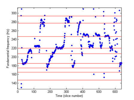
Figure 2. Fundamental frequency vs. time with lyrics. The red lines are the “ideal” frequencies found on a piano. The lyrics in the diagram are "I am sit - ting in the mor - ning at the di - ner on the cor-ner (breathe)"
2. Resample the complete 2-minute song into a constant-pitch audio sample. This sounds really strange, since the tempo of the song is lost, and the voice is a robotic one-note-song.
3. Extract some 15000 small pieces of this song which we now will call "formant waveforms". These waveforms are actually loopable, since we have chosen a fixed frequency for all of them.
4. Compare all formant waveforms, and find out which of them sounds the same.
5. Remove formant waveforms that are similar until there's only 255 of them left.
6. Make a couple of lists with this information:
* Which formant waveform shall we play now?
* At which fundamental frequency shall we play it?
* And with what volume?
This sounds pretty straight forward - but this does not solve the problem. We only had some 50kB of memory left for audio data. We want to chose a formant waveform size, to start with. A female voice does not contain any frequencies below 150Hz. That's why we love them, isn't it? So, lets choose a lowest frequency of 150Hz.
In order to handle sounds with frequencies down to 150Hz, each waveform is chosen to be 51 bytes long. Why? Because playing this waveform at 7812.5Hz will then produce a a fundamental frequency of
7812.5 / 51 = 153 Hz
Now, we need to store 255 waveforms, each 51 bytes in size, this is
255 * 51 = 13005 bytes of waveform data.
Fair enough.
And, for a two minute song, we need to store the tables with which formant, frequency and volume. To make a natural sound, these parameters should be changed approximately 150 times per second. We need
2 minutes * 60 secs per minute * 150 values per second * 3 bytes per row = 54000 bytes
Oops. Out-of-memory error. Again.
The answer, again, is compression. We want all of that data, but we need to make a compression scheme that will handle it. Fortunately, we only need to decompress these values 150 times per second. So, I chose a lossless compression scheme for these tables. The only functions that are available are "please give me the first value" and "please give me the next value".
As stated before, the formant waveforms are extracted. Since we only kept 255 waveforms out of originally 15000, we need to smoothen out the sound a little. We should probably make as smooth transitions from one waveform to another, to make the formant transitions as accurate as possible.
The audio will be rendered one period of the sound at a time. All audio parameters will need to be static during one period of the waveform. The reason for calculating one period of the sound at a time is to remove glitches and clicks when changing the audio parameters. If we did changes in the middle of a waveform, there would be an audible click at every parameter change. Now, changes occur at zero crossings of the audio output, which will be inaudible.
The available audio parameters that can be used with a basic version of the audio render loop are:
1. Audio pitch. The formant waveform can be resampled from 100% to 200% of the original speed.
2. "the current formant waveform" number. 0-255
3. "the current formant waveform" volume. 0-15
4. "the next formant waveform" number. 0-255
5. "the next formant waveform" volume. 0-15
The pseudo-code for this loop is:
WaveformIndex  = 0.0;

    SoundBufferIndex =  0;

    while WaveformIndex  < WaveformLength

    {

    SoundBuffer(SoundBufferIndex++)  = FormantWaveform[ThisWave][WaveformIndex]  * ThisVolume +  FormantWaveform[NextWave][WaveformIndex] * NextVolume;

    WaveformIndex =  WaveformIndex + AudioPitch/100;
    }


 Figure 3. The audio  render loop pseudo code
I previously said that the 6502 CPU had no hardware support for multiplication, so we need to cheat. This is the reason for having only 16 different volume levels. We need tables with premultiplied values. With 16 different volume levels (where volume multiplier of 0 is pretty silly, so volume level 0 is not silent, it is audible), we need 16 tables, with 256 values in each. This occupies
16 tables * 256 bytes = 4kB of volume table memory
And the floating point arithmetic with the WaveformIndex needs to be implemented with fixed point numbers.
Which leads us to the fully functional basic version of the audio render loop, which you can see in Figure 4 below.
  ldy #WaveformLength          ;y register is integer part of WaveformIndex throughout the whole loop

AudioRenderLoop:

  ldx ThisWaveform,y           ;read FormantWaveform[CurrentWave] into x register

  lda ThisVolumeTable,x        ;multiply it with ThisVolume, and put result in accumulator

  ldx NextWaveform,y           ;read FormantWaveform[NextWave] into x register

  adc NextVolumeTable+$0f00,x  ;multiply it with NextVolume, and add result to accumulator

  pha                          ;output the audio sample to the sound buffer in the 6502 stack

  lda WaveformIndexLSB         ;put the fractional part of WaveformIndex into accumulator

  sbc #AudioPitch              ;add the AudioPitch

  sta WaveformIndexLSB         ;save the new fractional part of the WaveformIndex in memory

  bcs AudioNoY                 ;if there was no carry from the fractional part, skip next instruction

  dey                          ;decrease the integer part of WaveformIndex due to fractional overflow

AudioNoY:

  dey                          ;decrease the integer part of WaveformIndex

  bpl AudioRenderLoop          ;If there's still more samples to process, go to top of loop again


Figure 4. The complete audio render loop.
There are a couple of tricks already used to speed this loop up. The WaveformIndex is decremented instead of incremented, since a comparison with zero is "for free", while comparing with WaveformLength costs us an assembly instruction.
And, the assembly code is written as self modifying code. The audio parameters are not sent to the audio render loop. They are directly written into the audio render code. And, to make the code run even faster, it is copied into a special area of the memory that is called zero page, which saves a clock cycle inside the loop where WaveformIndexLSB is written.
The school book example of speeding up computer algorithms by using loop unrolling does not work here. The audio render loop contains extensive use of self-modifying code, all these would need to be reworked into zero-page pointers instead - and the addressing of zero-page pointers cannot use registers x and y as above, since the 6502 CPU instruction set handle these differently. We would get rid of one branch instruction - but with the addedl overhead of zero-page pointers we would not gain anything by loop unrolling.
There's another trick used, not easily spotted, though. The output in the audio buffer needs to be 8-bit unsigned. The audio waveforms used as raw input are 8-bit signed. The solution of for-free translation from signed to unsigned arithmetics is in the VolumeTables. By adding a bias of 0x40 (=decimal 64), and making sure of always adding two and only two samples together, the signed data read from the ThisWaveform will end up being aligned to 0x80 (=decimal 128) after two passes through the volume tables.
Another, pretty advanced, digital audio topic is the Nyquist frequency (stated in 1928 by Harry Nyquist, a Swedish-American engineer) and the aliasing problem when resampling audio waveforms. To make a long story short, the WaveformTables should not contain any frequencies above 2kHz, since playing them at 200% pitch would introduce audible artifacts from signals in the frequency range above 2kHz. Refer to "wheels spinning backwards" on old Western films on TV, for instance.
We have used all the clock cycles that were available, and there is not much else we can do here. If we need to add something to the audio render loop, we will have to remove something as well.
We know that we don't have much memory to use. So, what about streaming the required data from tape or disk? Then we would not have to store the tables for waveform, volume and pitch for the whole 2-minute song.
If we start with the cassette, there is no way of getting 8-bit data from a cassette. The Commodore 64 has no fast enough AD-converter. But, there is a 1-bit interface from the cassette, and carefully toggling this bit will give us data. The normal tape loader uses 446 clock cycles for indicating a single “0”-bit, and 668 clock cycles for indicating a single “1” bit. The maximum transfer rate is 28 bits per 50Hz, which is 175 bytes per second. This is too little, hence the normal cassette is not good enough for streaming the data.
The turbo loaders uses 216 clock cycles for a “0” and 326 clock cycles for a “1”. This is 7.6 bytes per 50Hz frame, which is 381 bytes per second. This data rate is ok. But, the data is in bit 4 of a register, and we will need loads of CPU time to decode this bit. So, due to the lack of free CPU clock cycles, the turbo tape approach is not ok for streaming data.
The same result is with streaming from a 5.25” floppy disk. The bandwidth with a seriously well-timed disk turbo is 3kB per second. But, to grab one byte from the disk drive over a 2-pin serial interface requires approximately 90 clock cycles. And, we don't have any spare clock cycles lying around, so we will have to skip using the floppy drive for streaming music data. - Which is a pity, since we would get rid of some 26kB of tables if we could.
So, the complete memory map now looks like this:
$0000- |
Zero page registers |
$0040- |
Zero page self-modifying code |
$0100- |
Audio buffer and 6502 CPU stack |
$0200- |
Bootloader decrunch code |
$0258- |
Program start, Initialization code |
$0400- |
Loader screen text |
$0800- |
Audio effects code |
$1900- |
Which pitch to play |
$4a00- |
Which waveform to play |
$8500- |
Noise volume for 4kHz-15kHz range |
$8c00- |
Waveform Tables |
$c000- |
Calculated volume tables |
$d000- |
Tube distortion volume tables – hidden underneath VIC, SID and CIA registers. |
$e000- |
Custom charset graphics |
$e800- |
Pre-calculated tables for sub bass frequencies, auto- tune, waveform pointers and LSR. |
$ee00- |
Demo text and video code |
$fc00- |
Screen memory |
Figure 5. Memory layout
As stated before, we want to implement time stretch, vocoding, auto-tune, sub bass, equalizer, echo, tube distortion, grungelizer, compression, dithering and a master gain. And, we don't have any spare clock cycles left.
Fortunately, not all of these effects needs to be done in the digital domain. If we had to add an effect, we would have to remove something from the audio render loop.
We can start with the "easy" ones. The ones that can be handled in the analog domain by features in the Commodore 64 audio chip "SID". The SID chip has a master gain setting, that we can use. This is analog, and has a 16-level setting that we can use.
Fine, only 10 audio effects to go.
Actually, the dithering is also handled by the SID chip. By using one of the three SID channels for playing low-level dithering noise, this will effectively act as an added dithering noise in the analog part of the audio chain.
Dither is an intentionally applied form of noise used to randomize quantization error, preventing noise at discrete frequencies in an audio recording, that are more objectionable than uncorrelated noise.
Technically speaking, the applied analog noise is not dithering noise, since this would require some kind of feedback loop and normally some kind of sigma-delta-modulation. The correct term would be colored masking noise. Anyway, if you can live with the fact that this solution is colored masking noise and not dithering, we're done with this as well.
Fine, only 9 audio effects to go.
The sub bass synthesis is another part where the SID chip can help us. In fact, this is the part where the SID chip does excel. Did you know that today in 2010 you can buy hardware synthesizers, widely used in modern pop music production, that uses the SID chip? They are used for fat bass sounds, mostly. Which means that the sub bass sound you hear, is in fact the SID chip using one of its oscillators to play a triangle waveform. Effect solved.
Now, there's only 8 audio effects left.
The last effect that we can use the SID chip for is the equalizer. The low, band and high pass filters are all part of the analog side of the SID chip, so is the resonance setting and the cutoff level. We couldn't have done it in the digital domain, so SID saves the day.
With 7 audio effects to go, we still have not changed the audio render loop at all.
As much as possible, we need to avoid having to do calculations inside the audio render loop. Any effect that can live outside the render loop, we should keep outside the render loop. But, the only five parameters that we can change are AudioPitch, ThisWaveform, ThisVolume, NextWaveform, NextVolume.
Fortunately, a couple of effects can be handled this way. Remember, the effects left are time stretch, vocoding, auto- tune, echo, tube distortion, grungelizer, and compression.
Auto-Tune is a patented audio processor created by the company Antares Audio Technologies. Auto-Tune uses a phase vocoder to correct pitch in vocal and instrumental performances. It is used to disguise off-key inaccuracies and mistakes, and has allowed singers to perform perfectly tuned vocal tracks without the need of singing in tune. Or, it was the end of "real musicians". Auto-Tune killed music. Your choise. Cher recorded the song "Believe" in 1998, which more or less defined Auto-Tune as a digital audio effect that could be used or mis-used at wish. It is described in US patent 5973252, Harold A. Hildebrand, "Pitch detection and intonation correction apparatus and method", granted 1999-10-26, assigned to Auburn Audio Technologies, Inc.
Auto-Tune is actually just a matter of changing the AudioPitch. Everything else is the same. We have a list already with the "desired audio pitch", and it is a matter of slightly adjusting this towards the "perfect pitch". Thankfully, we only have to do this once per calculated period in the audio, which is somewhere around 150-300 times per second. Problem solved.
Vocoding is almost the same as auto-tune, or at least, this version of vocoding is. There are more complicated vocoders that blends waveforms together in the frequency domain - but for the basic robotic vocoder sound, changing the pitch into a constant-pitch audio is enough. So, it is just to ignore the "desired audio pitch" and replace it with the vocoder pitch.
Bruce Haack's Electric Lucifer (1970) was the first rock album to include the vocoder and was followed several years later by Kraftwerk's Autobahn.
The definition of a vocoder is an analysis/synthesis system, mostly used for speech. In the encoder, the input is passed through a multi-band filter, each band is passed through an envelope follower, and the control signals from the envelope followers are communicated to the decoder. The decoder applies these (amplitude) control signals to corresponding filters in the (re)synthesizer. It is a 51-band envelope filter, since the extracted formant waveforms are filtered in the encoding step already, removing non-periodic harmonics.
The compressor algorithm normally works with look-ahead audio amplitude estimation, together with an automatic volume level. But, since we already have an extracted "this is the desired volume" list, the compressor is solved by adding the compressor level to the desired level. If the new level exceeds the maximum volume level, it is clipped to the maximum volume level. Again, we only have to do this calculation 150-300 times per second.
Now, we have 4 audio effects left. We're almost there, don't you think so?
You probably don't agree at first, but the time stretch algorithm is actually the easiest of those that are left. When stuck in the digital audio time domain, it is terribly complicated. But, the complicated part is already done in the audio compression algorithm. Remember, we did have a compressed list that will output ThisWaveformNumber, ThisVolume and ThisPitch. And the only functions available was "give me the first value" and "give me next value". Time stretch works by _not_ asking for the next value, but instead reusing the old ones, sometimes. This is used for playing the song slower than normal. For achieving a speedup, we just ask for the next value, throw it away, and directly ask for the value after that. This will make the song play faster.
The type of time stretch used in Cubase64 is the phase vocoder approach, which normally is done like this:
1. Compute the instantaneous frequency/amplitude relationship of the signal using the STFT, which is the discrete Fourier transform of a short, overlapping and smoothly windowed block of samples;
2. apply some processing to the Fourier transform magnitudes and phases (like resampling the FFT blocks); and
3. perform an inverse STFT by taking the inverse Fourier transform on each chunk and adding the resulting waveform chunks.
To be able to handle this in real-time, step 1, 2 and 3 are done already in the audio compression step, and so we can handle time stretch on-the-fly. Job done.
Three audio effects left. Echo, tube distortion and grungelizer.
We'll start with the grungelizer now. I think we need to take a look at the audio render loop algorithm once more. Currently, each sample is calculated as
FormantWaveform[ThisWave][WaveformIndex] * ThisVolume + FormantWaveform[NextWave][WaveformIndex] * NextVolume;
If we want to make sure that instead of 8-bit output we get 7 or 5 or whatever, we have the possibility of adding the filter to the audio render loop. It is actually just a matter of making a simple "and" with a constant. But there is a better way of making this filtering. Remember, we can't add anything to the audio render loop without removing something.
So, instead of adding an instruction that takes two clock cycles into the audio render loop, we will change the contents of the audio multiplication tables. All of the 4kB of volume table data will be changed to have lower resolution multiplication results. We do have to make loads of calculations for all the new tables, but we save 2 clock cycles from the audio render loop, and that's what's important this time.
Two audio effects left. Echo and tube distortion.
Tube distortion (or valve sound) is the characteristic sound associated with a vacuum tube-based audio amplifier. The audible significance of tube amplification on audio signals is a subject of continuing debate among audio enthusiasts.
The tube sound is often subjectively described as having a "warmth" and "richness", but the source of this is by no means agreed on. It may be due to the non-linear clipping that occurs with tube amps, or due to the higher levels of second-order harmonic distortion, common in single-ended designs resulting from the characteristics of the tube interacting with the inductance of the output transformer.
Soft clipping is a very important aspect of tube sound especially for guitar amplifiers, although a hi-fi amplifier should not normally ever be driven into clipping. A tube amplifier will reproduce a wave relatively linearly to a point, and as the signal moves beyond the linear range of the tube (into overload), it distorts the signal with a smooth curve instead of a sudden, sharp-edged cutoff as occurs with transistors.
We'll implement tube distortion by introducing a non-linear function into the audio signal chain. There are two ways of doing these calculations:
IR-switching technique
Diagonal Volterra Kernel
IR stands for Impulse Response, and IR-switching handles the non-linearities by selecting different convolution FIR-filters depending on the amplitude of the input signal. The first published papers about this was written by Bellini and Farina (1998) and Michael Kemp (1999).
The Diagonal Volterra Kernel uses multiple impulse responses, and convolutes these with AudioInput, AudioInput^2, AudioInput^3, etc.
Cubase64 calculates the non-linearity by using a second-order Diagonal Volterra Kernel with Impulse Responses of length 1. The mathematical equivalent is really simple:
AudioOut = AudioIn * k1 + AudioIn^2 * k2;
We do not want to do these calculations in real time, so we will have to incorporate the non-linearity into the volume tables as well. Even more so, we don't want to do these calculations at all on the 6502 CPU, so we're better of with a precalculated table with tube distortion. Do you remember the "hidden" memory underneath the VIC-II, SID, CIA and color RAM? There's 4kB of RAM there, and we could grab a ready-made copy of the tube-distorted volume tables from it. And apply the grungelizer's and filters when we make the copy. We will have to briefly pause the audio while the hidden memory is retrieved.
The tube distortion “high” setting is using exactly the precalculated table. The “low” setting is achieved by taking 50% of a normal linear volume table and 50% of the precalculated tube distortion table.
One audio effect left, echo. And this time, we do have to make a new audio render loop.
Electric echo effects have been used since the 1950s. The Echoplex is a tape delay effect, first made in 1959 that recreates the sound of an acoustic echo. Designed by Mike Battle, the Echoplex set a standard for the effect in the 1960s
Echo is the process of adding a copy of old audio with slightly lower volume. Fortunately, we already have a sound buffer which is full of old audio. The buffer is 256 bytes long, and with a sample rate of 7812.5Hz, this equals
256 / 7812.5 = 32.7 milliseconds of audio
The velocity of sound is approximately 343 m/s at a normal room temperature of about 20°C, so our largest sound delay of 32 milliseconds will emulate the sound travelling 343*0.032=11 meters, which is the same as us standing in the middle of a sphere-shaped room 5.5 meters from the walls.
If you want to find such an echo in Sweden, visit the Water Tower in Växjö. It's not a sphere shaped room, but the area below the Water Tower is half a sphere.
The feedback volume would be the relative damping that the material on the walls would make.
Well, it is time for a new audio render loop, this time with built-in echo: See Figure 6 below for the code, and please compare with the original audio render loop in Figure 4 above.
  ldy #WaveformLength          ;y register is integer part of WaveformIndex throughout the whole loop

EchoRenderLoop:

  ldx OldAudioAddress          ;read the old audio into the x register

  lda EchoFeedbackVolume,x     ;multiply it with the EchoFeedbackVolume

  ldx ThisWaveform,y           ;read FormantWaveform[CurrentWave] into x register

  adc ThisVolumeTable,x        ;multiply it with ThisVolume, and add result to the accumulator

  pha                          ;output the audio sample to the sound buffer in the 6502 stack

  dec OldAudioAddressLSB       ;jump one audio sample forward in the old audio buffer

  lda WaveformIndexLSB         ;put the fractional part of WaveformIndex into accumulator

  sbc #AudioPitch              ;add the AudioPitch

  sta WaveformIndexLSB         ;save the new fractional part of the WaveformIndex in memory

  bcs EchoNoY                  ;if there was no carry from the fractional part, skip next instruction

  dey                          ;decrease the integer part of WaveformIndex due to fractional overflow

EchoNoY:

  dey                          ;decrease the integer part of WaveformIndex

  bpl EchoRenderLoop           ;If there's still more samples to process, go to top of loop again
 Figure 6. The complete audio render loop, with echo.
The only changes is that we had to remove the smooth transition from the current FormantWaveform into the next one, replace it with adding the echo and the current formant waveform.
We gained one clock cycle since the reading of the OldAudioAddress can be done without using the y register as offset. But, we lost 5 clock cycles when we had to decrement the OldAudioAddressLSB. So, the echo version of the audio render loop do take another 4 clock cycles for every sample that we calculate.
We already have a register y that is decreasing, how come this isn't used in addressing the "old audio"? The simple answer to that is that we need wrapping. The old audio buffer is located between $0100-$01ff in memory. With a fixed start position with the y register (it's either WaveformLength or WaveformLength-1 due to reasons not presented in this paper) – there is no way of efficiently using a decreasing y register to implement a wrapping buffer. This would need the y register to be started at the same place as our buffer, which will be more complicated than the loop above.
This concludes all of the audio effects. And they can all be used simultaneously. In real time.
On a home computer built in 1982.
Internet is your friend. Search and you will find. This is a list with recommended searches.
In order to understand 6502 CPU optimizations, you need a table with 6502 opcodes and clock cycle count.
You probably also want to take a look at the Commodore 64 memory map, it shows all special addresses that the Commodore 64 has for its VIC-II, SID and CIA chips, for instance.
You should want to read more about the audio effects used. They have names such as auto-tune, pitch vocoder, echo, time stretch, audio gain, audio quantization, dithering noise, equalizer and audio compressor (not to be mixed up with audio compression, which is a completely different cup of tea).
If you find a reference to something called "c64mp3", this refers to an older version of the Cubase64 demo, which "only" played the Tom's Diner-song, but without the audio effects. The mp3-part of the name is of course a joke, as I guess you understand by now.
For more information about the Commodore 64 “sceners”, people still programming audio-visual entertainment on this old home computer, see the Commodore 64 scene database, http://csdb.dk
No, you can't use all audio effects at the same time. There is one exception. The sub bass synthesizer and the dithering noise have to share one SID oscillator, which means that if you enable dithering, the sub bass will be silent. And if you enable the sub bass, the dithering will be lost.
And, since the echo version of the audio render loop did take four extra clock cycles per sample, the CPU will be overloaded if you try to use 200% time stretch at the same time as echo is turned on. Sometimes, the sound buffer will be consumed faster than the echo render loop can fill it. Using the joystick at the same time will make matters worse, since graphical updates have higher priority than audio rendering. Users of the PC versions of Cubase would probably like to have it this way as well, but they are stuck in a world where audio rendering has priority, and the Windows operating system will crash quite violently if the audio renderings takes too much CPU power.
This Cubase64 demo does things that retail Cubase version cannot do. There's no such thing as real-time time stretch in Cubase. Cubase can only do off-line time stretch, writing audio to disk before playing it. This is due to the inherent timeline scale being identical for all tracks in a song. If you started to allow time stretching for one track only, it would need its own timescale, and the layout of the tracks would need reworking. It could be done, but I understand the reasons for not incorporating real-time time stretch in Cubase.
And, you can introduce digital artifacts with the echo render loop. There's no CPU power left to handle digital clipping, so any kind of arithmetic overflow will be heard not as distortion, but rather as high-volume noise. That's the reason for the Echo input gain setting. It could be hidden for the user, but it's funnier when it's there, I think.
The company behind the Cubase range of products, Steinberg, has nothing to do with this, as I hope you've already guessed. They have never made any official statements about Cubase and Commodore 64. Cubase is an excellent product, in my opinion. It does have its history of bugs and crappy behavior, but compared with the fun you get out of it, it's all worth it.
There's probably loads of errors in this text. If you did find one, I'd be happy if I got to know about it. You'll find my contact details at this webpage, http://mahoney.c64.org
Some of the "errors" are deliberate, since telling the whole truth and nothing but the truth would miss the educational flow of the text. If you want the full Monty on the run, please read the source code of the encoder and cubase64 demo. It's all there. unabridged. And probably completely incomprehensible to 99.9% of the human population.
Most of the comments found in the source code are meaningful. But there are traces of work-in-progress comments that should have been cleaned up long ago. The source code is correct, and most of the comments are too. If you find your way around the code, it's a fun read. But, it is not for the faint of heart, and please mind the gap.
Thanks for reading. I hope you have learned something new and I hope you feel it was time well spent. Please stop by my homepage http://mahoney.c64.org and give me a comment or two.
Or even better, head over to http://www.livet.se/visa and listen to and watch me and my friends sing Commodore 64 music a cappella - and buy a CD or two!
Best Regards, Pex 'Mahoney' Tufvesson, Lund, Sweden, October 2010.
| Pex 'Mahoney' Tufvesson, M.Sc.EE., has been programming computers since 1979. PET, ABC-80, Sinclair ZX Spectrum, Commodore 64, Amiga 500, Nintendo 64, Mac and PC. He's currently working as a hardware engineer, creating chip designs, and is the webmaster of a couple of websites like http://www.livet.se/ord which is a proverb collection. He's a musician with his own a cappella group Visa Röster. You'll find more about Pex Tufvesson on his homepage http://mahoney.c64.org |  |
Since you're already visiting my homepage, head over to my timeline and have a look yourself at all the thing you could do while not watching TV.
Nothing else to do? Continue here: Mahoney's timeline.